First, you'll need to download the 1Sheeld application in your mobile phone. I chose to do the camera shield using Arduino board, breadboard, jumper wires, pushbutton, and 1Sheeld board. http://1sheeld.com/tutorials/special-shields/ I used a simple set up for the push button. The website above doesn't provide schematics and I wasn't skilled enough to come up with my own set up. Consequently I initially used my classmate's set up, but it didn't work on my laptop so I used Mr. Robert's set up. During the set up process, I had difficulty trying to connect my laptop with the 1Sheeld board. There were 3 ports; 2 of them include the word 'bluetooth' in the port's name and the other one had the word 'USB' in the name. I didn't know which one is the correct port so I tried connecting to all of them, and in the end the USB port worked. When uploading the code from the website, you'll need to use Google Chrome, and on the 1Sheeld, push the button to the right to upload the code. When you're done uploading the code, push the button to the left. Next, turn on bluetooth from your phone's 1Sheeld app. It was hectic here since my classmates and I were trying to connect our phone (using bluetooth) all at the same time and so we struggled to connect the device because the we didn't know which device was ours. |
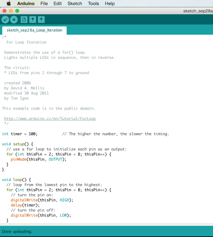
I directly uploaded the code through the sketch on the website. Select "Arduino Uno" in the left bar below the sketch, and then select the port and upload the code (using bluetooth may drain your phone battery really fast). Go to the camera shield in the app, and now when you push the button, the camera on your phone should snap a photo! (I don't know why mine and my classmates' phone camera continuously snapped photos even though we only pressed the button once. It worked well for Mr. Robert's phone though). The quality of the photos are not that good and every time the camera snaps the flash used (I don't know why flash is turned on; perhaps it is automatic?). Below are some random photos I took using this experiment.
0 Comments
The Graph is used to show how to send a byte of data from Arduino to a personal computer and graph the result. The graph is displayed through the program Processing, while the actual set up uses the program Arduino. Although my set up didn't work, I got a chance to try and play around with my classmate's set up. Turning the potentiometer (POT) left and right changes the graph's appearance (I think it's called the frequency?). My classmate played with it until the POT broke and turned the graph into weird alignments. I didn't take a photo or a video for this experiment, but on the right is a photo (from the tutorial website) of how the graph should look like. In the tutorial, the codes for Processing and Arduino are combined together, however, I separated them below so that it'll be easier to use. Processing Code: // Graphing sketch // This program takes ASCII-encoded strings // from the serial port at 9600 baud and graphs them. It expects values in the // range 0 to 1023, followed by a newline, or newline and carriage return // Created 20 Apr 2005 // Updated 24 Nov 2015 // by Tom Igoe // This example code is in the public domain. import processing.serial.*; Serial myPort; // The serial port int xPos = 1; // horizontal position of the graph float inByte = 0; void setup () { // set the window size: size(400, 300); // List all the available serial ports // if using Processing 2.1 or later, use Serial.printArray() println(Serial.list()); // I know that the first port in the serial list on my mac // is always my Arduino, so I open Serial.list()[0]. // Open whatever port is the one you're using. myPort = new Serial(this, Serial.list()[0], 9600); // don't generate a serialEvent() unless you get a newline character: myPort.bufferUntil('\n'); // set inital background: background(0); } void draw () { // draw the line: stroke(127, 34, 255); line(xPos, height, xPos, height - inByte); // at the edge of the screen, go back to the beginning: if (xPos >= width) { xPos = 0; background(0); } else { // increment the horizontal position: xPos++; } } void serialEvent (Serial myPort) { // get the ASCII string: String inString = myPort.readStringUntil('\n'); if (inString != null) { // trim off any whitespace: inString = trim(inString); // convert to an int and map to the screen height: inByte = float(inString); println(inByte); inByte = map(inByte, 0, 1023, 0, height); } } /* Max/MSP v5 patch for this example ----------begin_max5_patcher---------- 1591.3oc0YszbaaCD9r7uBL5RalQUAO3CvdyS5zVenWZxs5NcfHgjPCIfJIT RTxj+6AOHkoTDooroUs0AQPR73a+1cwtK3WtZxzEpOwqlB9YveAlL4KWMYh6 Q1GLo99ISKXeJMmU451zTUQAWpmNy+NM+SZ2y+sR1l02JuU9t0hJvFlNcMPy dOuBv.U5Rgb0LPpRpYBooM3529latArTUVvzZdFPtsXAuDrrTU.f.sBffXxL vGE50lIHkUVJXq3fRtdaoDvjYfbgjujaFJSCzq4.tLaN.bi1tJefWpqbO0uz 1IjIABoluxrJ1guxh2JfPO2B5zRNyBCLDFcqbwNvuv9fHCb8bvevyyEU2JKT YhkBSWPAfq2TZ6YhqmuMUo0feUn+rYpY4YtY+cFw3lUJdCMYAapZqzwUHX8S crjAd+SIOU6UBAwIygy.Q1+HAA1KH6EveWOFQlitUK92ehfal9kFhUxJ3tWc sgpxadigWExbt1o7Ps5dk3yttivyg20W0VcSmg1G90qtx92rAZbH4ez.ruy1 nhmaDPidE07J+5n2sg6E6oKXxUSmc20o6E3SPRDbrkXnPGUYE.i5nCNB9TxQ jG.G0kCTZtH88f07Rt0ZMMWUw8VvbKVAaTk6GyoraPdZff7rQTejBN54lgyv HE0Ft7AvIvvgvIwO23jBdUkYOuSvIFSiNcjFhiSsUBwsUCh1AgfNSBAeNDBZ DIDqY.f8.YjfjV1HAn9XDTxyNFYatVTkKx3kcK9GraZpI5jv7GOx+Z37Xh82 LSKHIDmDXaESoXRngIZQDKVkpxUkMCyXCQhcCK1z.G457gi3TzMz4RFD515F G3bIQQwcP3SOF0zlkGhiCBQ1kOHHFFlXaEBQIQnCwv9QF1LxPZ.A4jR5cyQs vbvHMJsLll01We+rE2LazX6zYmCraRrsPFwKg1ANBZFY.IAihr8Ox.aH0oAL hB8nQVw0FSJiZeunOykbT6t3r.NP8.iL+bnwNiXuVMNJH9H9YCm89CFXPBER bz422p8.O4dg6kRxdyjDqRwMIHTbT3QFLskxJ8tbmQK4tm0XGeZWF7wKKtYY aTAF.XPNFaaQBinQMJ4QLF0aNHF0JtYuHSxoUZfZY6.UU2ejJTb8lQw8Fo5k Rv6e2PI+fOM71o2ecY1VgTYdCSxxUqLokuYq9jYJi6lxPgD2NIPePLB0mwbG YA9Rgxdiu1k5xiLlSU6JVnx6wzg3sYHwTesB8Z5D7RiGZpXyvDNJY.DQX3.H hvmcUN4bP1yCkhpTle2P37jtBsKrLWcMScEmltOPv22ZfAqQAdKr9HzATQwZ q18PrUGt6Tst2XMCRUfGuhXs6ccn23YloomMqcTiC5iMGPsHsHRWhWFlaenV XcqwgCQiGGJzptyS2ZMODBz6fGza0bzmXBj7+DA94bvpR01MffAlueO7HwcI pWCwmzJdvi9ILgflLAFmyXB6O7ML0YbD26lenmcGxjVsZUN+A6pUK7AtTrPg M+eRYG0qD9j4I7eEbco8Xh6WcO.or9XDC6UCiewbXHkh6xm5LiPEkzpJDRTu mEB44Fgz4NCtJvX.SM1vo2SlTCZGAe7GZu6ahdRyzFOhYZ+mbVVSYptBw.K1 tboIkatIA7c1cTKD1u.honLYV04VkluHsXe0szv9pQCE9Ro3jaVB1o15pz2X zYoBvO5KXCAe0LCYJybE8ZODf4fV8t9qW0zYxq.YJfTosj1bv0xc.SaC0+AV 9V9L.KKyV3SyTcRtmzi6rO.O16USvts4B5xe9EymDvebK0eMfW6+NIsNlE2m eqRyJ0utRq13+RjmqYKN1e.4d61jjdsauXe3.2p6jgi9hsNIv97CoyJ01xzl c3ZhUCtSHx3UZgjoEJYqNY+hYs5zZQVFW19L3JDYaTlMLqAAt1G2yXlnFg9a 53L1FJVcv.cOX0dh7mCVGCLce7GFcQwDdH5Ta3nyAS0pQbHxegr+tGIZORgM RnMj5vGl1Fs16drnk7Tf1XOLgv1n0d2iEsCxR.eQsNOZ4FGF7whofgfI3kES 1kCeOX5L2rifbdu0A9ae2X.V33B1Z+.Bj1FrP5iFrCYCG5EUWSG.hhunHJd. HJ5hhnng3h9HPj4lud02.1bxGw. -----------end_max5_patcher----------- */ Arduino Code:
/* Graph A simple example of communication from the Arduino board to the computer: the value of analog input 0 is sent out the serial port. We call this "serial" communication because the connection appears to both the Arduino and the computer as a serial port, even though it may actually use a USB cable. Bytes are sent one after another (serially) from the Arduino to the computer. You can use the Arduino serial monitor to view the sent data, or it can be read by Processing, PD, Max/MSP, or any other program capable of reading data from a serial port. The Processing code below graphs the data received so you can see the value of the analog input changing over time. The circuit: Any analog input sensor is attached to analog in pin 0. created 2006 by David A. Mellis modified 9 Apr 2012 by Tom Igoe and Scott Fitzgerald This example code is in the public domain. http://www.arduino.cc/en/Tutorial/Graph */ void setup() { // initialize the serial communication: Serial.begin(9600); } void loop() { // send the value of analog input 0: Serial.println(analogRead(A0)); // wait a bit for the analog-to-digital converter // to stabilize after the last reading: delay(2); } Tutorial Although it is a simple set up using only one LED, a few jumper wires, a resistor, and an Arduino board, I couldn't get mine to work because my laptop is a MAC, not a PC (My classmate's laptops were all PC so their set up went well). For this one and the next, you'll need to download the program "Processing." In the original website, the given codes for Arduino and Processing are not separated. I've separated them below for easier use. After uploading the codes to both programs, you can use your laptop cursor to control the LED by dragging it left and right on the gradient scale on Processing in order to dim the LED. Processing Code: // Dimmer - sends bytes over a serial port // by David A. Mellis //This example code is in the public domain. import processing.serial.*; Serial port; void setup() { size(256, 150); println("Available serial ports:"); // if using Processing 2.1 or later, use Serial.printArray() println(Serial.list()); // Uses the first port in this list (number 0). Change this to // select the port corresponding to your Arduino board. The last // parameter (e.g. 9600) is the speed of the communication. It // has to correspond to the value passed to Serial.begin() in your // Arduino sketch. port = new Serial(this, Serial.list()[0], 9600); // If you know the name of the port used by the Arduino board, you // can specify it directly like this. //port = new Serial(this, "COM1", 9600); } void draw() { // draw a gradient from black to white for (int i = 0; i < 256; i++) { stroke(i); line(i, 0, i, 150); } // write the current X-position of the mouse to the serial port as // a single byte port.write(mouseX); } /* Max/MSP v5 patch for this example ----------begin_max5_patcher---------- 1008.3ocuXszaiaCD9r8uhA5rqAeHIa0aAMaAVf1S6hdoYQAsDiL6JQZHQ2M YWr+2KeX4vjnjXKKkKhhiGQ9MeyCNz+X9rnMp63sQvuB+MLa1OlOalSjUvrC ymEUytKuh05TKJWUWyk5nE9eSyuS6jesvHu4F4MxOuUzB6X57sPKWVzBLXiP xZtGj6q2vafaaT0.BzJfjj.p8ZPukazsQvpfcpFs8mXR3plh8BoBxURIOWyK rxspZ0YI.eTCEh5Vqp+wGtFXZMKe6CZc3yWZwTdCmYW.BBkdiby8v0r+ST.W sD9SdUkn8FYspPbqvnBNFtZWiUyLmleJWo0vuKzeuj2vpJLaWA7YiE7wREui FpDFDp1KcbAFcP5sJoVxp4NB5Jq40ougIDxJt1wo3GDZHiNocKhiIExx+owv AdOEAksDs.RRrOoww1Arc.9RvN2J9tamwjkcqknvAE0l+8WnjHqreNet8whK z6mukIK4d+Xknv3jstvJs8EirMMhxsZIusET25jXbX8xczIl5xPVxhPcTGFu xNDu9rXtUCg37g9Q8Yc+EuofIYmg8QdkPCrOnXsaHwYs3rWx9PGsO+pqueG2 uNQBqWFh1X7qQG+3.VHcHrfO1nyR2TlqpTM9MDsLKNCQVz6KO.+Sfc5j1Ykj jzkn2jwNDRP7LVb3d9LtoWBAOnvB92Le6yRmZ4UF7YpQhiFi7A5Ka8zXhKdA 4r9TRGG7V4COiSbAJKdXrWNhhF0hNUh7uBa4Mba0l7JUK+omjDMwkSn95Izr TOwkdp7W.oPRmNRQsiKeu4j3CkfVgt.NYPEYqMGvvJ48vIlPiyzrIuZskWIS xGJPcmPiWOfLodybH3wjPbMYwlbFIMNHPHFOtLBNaLSa9sGk1TxMzCX5KTa6 WIH2ocxSdngM0QPqFRxyPHFsprrhGc9Gy9xoBjz0NWdR2yW9DUa2F85jG2v9 FgTO4Q8qiC7fzzQNpmNpsY3BrYPVJBMJQ1uVmoItRhw9NrVGO3NMNzYZ+zS7 3WTvTOnUydG5kHMKLqAOjTe7fN2bGSxOZDkMrBrGQ9J1gONBEy0k4gVo8qHc cxmfxVihWz6a3yqY9NazzUYkua9UnynadOtogW.JfsVGRVNEbWF8I+eHtcwJ +wLXqZeSdWLo+FQF6731Tva0BISKTx.cLwmgJsUTTvkg1YsnXmxDge.CDR7x D6YmX6fMznaF7kdczmJXwm.XSOOrdoHhNA7GMiZYLZZR.+4lconMaJP6JOZ8 ftCs1YWHZI3o.sIXezX5ihMSuXzZtk3ai1mXRSczoCS32hAydeyXNEu5SHyS xqZqbd3ZLdera1iPqYxOm++v7SUSz -----------end_max5_patcher----------- */ Arduino Code:
/* Dimmer Demonstrates the sending data from the computer to the Arduino board, in this case to control the brightness of an LED. The data is sent in individual bytes, each of which ranges from 0 to 255. Arduino reads these bytes and uses them to set the brightness of the LED. The circuit: LED attached from digital pin 9 to ground. Serial connection to Processing, Max/MSP, or another serial application created 2006 by David A. Mellis modified 30 Aug 2011 by Tom Igoe and Scott Fitzgerald This example code is in the public domain. http://www.arduino.cc/en/Tutorial/Dimmer */ const int ledPin = 9; // the pin that the LED is attached to void setup() { // initialize the serial communication: Serial.begin(9600); // initialize the ledPin as an output: pinMode(ledPin, OUTPUT); } void loop() { byte brightness; // check if data has been sent from the computer: if (Serial.available()) { // read the most recent byte (which will be from 0 to 255): brightness = Serial.read(); // set the brightness of the LED: analogWrite(ledPin, brightness); } } The ASCII Table demonstrates Arduino's advanced serial output functions but generating on the serial monitor. This one is very simple. All you need was the Arduino board, then connect it to your laptop to upload the code. Here is the Tutorial.
IR Distance Sensor
IR Distance sensor code: // Declare the used sensor pin <br>int sensorPin = A0; int LED = 13; // Declare the connected LED void setup(){ // Start the Serial connection Serial.begin(9600); } void loop(){ // Read the analog value of the sensor int val = analogRead(A0); // Print the value over Serial Serial.println(val); // Write the value to the LED using PWM analogWrite(LED, val); // Wait a little for the data to print delay(100); } After you've uploaded the code, open up either the serial monitor or the serial plotter to see if you've completed the circuit. I played around with the distance, and also tried using other sizes LED. I have also tried putting two tiny LED together. The only difficult thing is to figure out how I will adapt the set up to my Halloween project. And what exactly will I make? To answer that question, I tried duplicating a simple Halloween project. Halloween Spooky SkullFollowing this tutorial, we'll be using the Fade code. However, it didn't give me the result I wanted (I doesn't 'fade'-- the result was more like the one from Blink code. ). Materials: 1. Arduino board 2. RGB LED So I tried to follow this tutorial instead of the fade one -- in which I'm not even going to post the link for the fade one because it doesn't work and there's no point to sharing the link if we won't make any good use out of it. However, I'll post the code to the fade one that I've tried. I didn't really understand how the fading work with that code. Even though I modified the numbers, it seemed like the LED turn on duration is just shorter. I tried everything but there was no 'fade effect.' Code: int ledPin = 13; void setup() { } void loop() { for(int fadeValue = 0 ; fadeValue <= 10; fadeValue +=10) { analogWrite(ledPin, fadeValue); delay(60); } for(int fadeValue = 255 ; fadeValue >= 10; fadeValue -=10) { analogWrite(ledPin, fadeValue); delay(200); } } The tutorial hyperlinked above have a schematic, but I didn't follow the schematic. I modified the code a little. You'll also need two paper clips and an A4 paper, and a pair of scissors to cut out the eyes on the paper. Put the RGB LED in the following pins: Gnd, 13, 12, 11. Then just plugged in the USB cable to your laptop and upload the code below. Put the crafted paper spooky skull on top of the RGB, run the code, and voila!
The fade effect works! But I have one problem-- the sequence didn't include red light when it should. I tried modifying things and changing the code, but I couldn't find out what was wrong. I am however, satisfied with the result and the modification I've made. Halloween Spooky Skull Code: // RGB LED Light Up and Cycle Colors // From Interactive Art Session at 757 Makerspace on October 17, 2015 // Design by Akin Yildiz and Beau Turner // Global Variables Go Here const int redPin = 13; const int greenPin = 12; const int bluePin = 11; // The setup section runs one time at the start of the program void setup() { setColorRgb(0,0,0); // Set the the LED to off } //The loop section repeats over and over void loop() { unsigned int rgbColor[3]; rgbColor[0] = 255; // Start Red rgbColor[1] = 0; rgbColor[2] = 0; // Cycle colors + & - for (int decColor = 0; decColor < 3; decColor += 1) { int incColor = decColor == 2 ? 0 : decColor + 1; // Cross-fade colors for(int i = 0; i < 255; i += 1) { rgbColor[decColor] -= 1; rgbColor[incColor] += 1; setColorRgb(rgbColor[0], rgbColor[1], rgbColor[2]); delay(5); } } } void setColorRgb(unsigned int red, unsigned int green, unsigned int blue) { analogWrite(redPin, red); analogWrite(greenPin, green); analogWrite(bluePin, blue); } This time we're using an ultrasonic sensor (distance 2cm - 4m). The ultrasonic sensor emits ultra sound at 40,000 Hz and if there is an object on its path, the ultra sound will bounce back to the module. I think we'll be using this in our Halloween project. We could make a skull or a pumpkin move or turn on LED in the eyes! Tutorial Materials: 1. Arduino board 2. HC-SR04 Ultrasonic Sensor 3. LED 4. resistors 5. jumper wires It was a little confusing for me, but I managed to complete the circuit and get it to work. I added the battery so that it'll give more power to the circuit. Watch the video below to see how mine functioned. There is a part 2 to the experiment but I couldn't get it to work on my set up (it works on PCs though), you might want to try it! . Before that, you'll need to download the program: Processing. I'd problem with a few lines of the code in the part 2 experiment. When I open up the sketch from Processing, I'd to change the code to: myPort = new Serial(this, "/dev/cu.usbmodem1451", 9600); in order to get it connected. However, even when it's connected, I think there was something wrong with my set up and so I didn't successfully complete the second part of the experiment. Code (Experiment Part1):
/* HC-SR04 Ping distance sensor] VCC to arduino 5v GND to arduino GND Echo to Arduino pin 13 Trig to Arduino pin 12 Red POS to Arduino pin 11 Green POS to Arduino pin 10 560 ohm resistor to both LED NEG and GRD power rail More info at: http://goo.gl/kJ8Gl Original code improvements to the Ping sketch sourced from Trollmaker.com Some code and wiring inspired by http://en.wikiversity.org/wiki/User:Dstaub/robotcar */ #define trigPin 13 #define echoPin 12 #define led 11 #define led2 10 void setup() { Serial.begin (9600); pinMode(trigPin, OUTPUT); pinMode(echoPin, INPUT); pinMode(led, OUTPUT); pinMode(led2, OUTPUT); } void loop() { long duration, distance; digitalWrite(trigPin, LOW); // Added this line delayMicroseconds(2); // Added this line digitalWrite(trigPin, HIGH); // delayMicroseconds(1000); - Removed this line delayMicroseconds(10); // Added this line digitalWrite(trigPin, LOW); duration = pulseIn(echoPin, HIGH); distance = (duration/2) / 29.1; if (distance < 4) { // This is where the LED On/Off happens digitalWrite(led,HIGH); // When the Red condition is met, the Green LED should turn off digitalWrite(led2,LOW); } else { digitalWrite(led,LOW); digitalWrite(led2,HIGH); } if (distance >= 200 || distance <= 0){ Serial.println("Out of range"); } else { Serial.print(distance); Serial.println(" cm"); } delay(500); } Loop"Often you want to iterate over a series of pins and do something to each one. For instance, this example blinks 6 LEDsattached to the Arduino or Genuino by using a for() loop to cycle back and forth through digital pins 2-7. The LEDS are turned on and off, in sequence, by using both the digitalWrite() and delay() functions ." Tutorial In my opinion, it's almost like the LED sequence that we attempted earlier-- except this time, our experiment was successful. It might be because the schematic is more accurate than the previous ones. I didn't struggle in this experiment. Perhaps it's because I was more careful and observant than before. I was the last to start the set up, and was the second to successfully complete the experiment. Materials: 1. Arduino board 2. Breadboard 3. 220 ohm resistors 4. 6 LEDs 5. jumper wires Loop Code: /* For Loop Iteration Demonstrates the use of a for() loop. Lights multiple LEDs in sequence, then in reverse. The circuit: * LEDs from pins 2 through 7 to ground created 2006 by David A. Mellis modified 30 Aug 2011 by Tom Igoe This example code is in the public domain. http://www.arduino.cc/en/Tutorial/ForLoop */ int timer = 100; // The higher the number, the slower the timing. void setup() { // use a for loop to initialize each pin as an output: for (int thisPin = 2; thisPin < 8; thisPin++) { pinMode(thisPin, OUTPUT); } } void loop() { // loop from the lowest pin to the highest: for (int thisPin = 2; thisPin < 8; thisPin++) { // turn the pin on: digitalWrite(thisPin, HIGH); delay(timer); // turn the pin off: digitalWrite(thisPin, LOW); } // loop from the highest pin to the lowest: for (int thisPin = 7; thisPin >= 2; thisPin--) { // turn the pin on: digitalWrite(thisPin, HIGH); delay(timer); // turn the pin off: digitalWrite(thisPin, LOW); } } In this video above, I used the code from the tutorial. In the video below, I adjusted the speed timer = 20. The higher the number, the slower the timing. ArrayArray is similar to loop, except that it doesn't go in linear, straight forward sequence. Here is my analogy: If loop goes 12345, array puts it in a different pattern like this 15324. The set up is the same as the loop, therefore if you're already working on the loop, you can just copy and paste the array code: Tutorial This could be used to plan a LED sequence for the halloween props project! I kept this experiment for tomorrow's (Thursday) Tech Club meeting-- so that I can show this cool stuff to the rest of my club members. :D
Array Code: /* Arrays Demonstrates the use of an array to hold pin numbers in order to iterate over the pins in a sequence. Lights multiple LEDs in sequence, then in reverse. Unlike the For Loop tutorial, where the pins have to be contiguous, here the pins can be in any random order. The circuit: * LEDs from pins 2 through 7 to ground created 2006 by David A. Mellis modified 30 Aug 2011 by Tom Igoe This example code is in the public domain. http://www.arduino.cc/en/Tutorial/Array */ int timer = 100; // The higher the number, the slower the timing. int ledPins[] = { 2, 7, 4, 6, 5, 3 }; // an array of pin numbers to which LEDs are attached int pinCount = 6; // the number of pins (i.e. the length of the array) void setup() { // the array elements are numbered from 0 to (pinCount - 1). // use a for loop to initialize each pin as an output: for (int thisPin = 0; thisPin < pinCount; thisPin++) { pinMode(ledPins[thisPin], OUTPUT); } } void loop() { // loop from the lowest pin to the highest: for (int thisPin = 0; thisPin < pinCount; thisPin++) { // turn the pin on: digitalWrite(ledPins[thisPin], HIGH); delay(timer); // turn the pin off: digitalWrite(ledPins[thisPin], LOW); } // loop from the highest pin to the lowest: for (int thisPin = pinCount - 1; thisPin >= 0; thisPin--) { // turn the pin on: digitalWrite(ledPins[thisPin], HIGH); delay(timer); // turn the pin off: digitalWrite(ledPins[thisPin], LOW); } }
This experiment was pretty straight forward and simple. I think I'm improving a whole lot because now I kind of am able to combine codes together. I still don't fully understand the syntax of it, but I think I'll understand it eventually. It was difficult to film this experiment by myself because I don't have free hand to turn the POT, and the three cables always get loose or fall off. I think everyone of my classmates successfully finish this experiment. In class today, we were inspired by a maker project video, and so we decided that we wanted to make cool Halloween props! I think it'll be exciting to see what we come up with or what we'll be making!
Switch Statement Code:
/* Switch statement Demonstrates the use of a switch statement. The switch statement allows you to choose from among a set of discrete values of a variable. It's like a series of if statements. To see this sketch in action, but the board and sensor in a well-lit room, open the serial monitor, and and move your hand gradually down over the sensor. The circuit: * photoresistor from analog in 0 to +5V * 10K resistor from analog in 0 to ground created 1 Jul 2009 modified 9 Apr 2012 by Tom Igoe This example code is in the public domain. http://www.arduino.cc/en/Tutorial/SwitchCase */ // these constants won't change. They are the // lowest and highest readings you get from your sensor: const int sensorMin = 0; // sensor minimum, discovered through experiment const int sensorMax = 600; // sensor maximum, discovered through experiment void setup() { // initialize serial communication: Serial.begin(9600); } void loop() { // read the sensor: int sensorReading = analogRead(A0); // map the sensor range to a range of four options: int range = map(sensorReading, sensorMin, sensorMax, 0, 3); // do something different depending on the // range value: switch (range) { case 0: // your hand is on the sensor Serial.println("dark"); break; case 1: // your hand is close to the sensor Serial.println("dim"); break; case 2: // your hand is a few inches from the sensor Serial.println("medium"); break; case 3: // your hand is nowhere near the sensor Serial.println("bright"); break; } delay(1); // delay in between reads for stability } After getting things to work the way it should, I tried to modify the code so that it would include LED and when I use my finger to cover the photoresistor the LED would turn on. I didn't manage to do that because I didn't input the codes correctly. It was then 5 minutes until the bell rang, so we decided to pack up. ![]() After experimenting with the servo motor, now we're going to be experimenting with a stepper motor. Stepper motors "are DC motors that move in discrete steps. They have multiple coils that are organized in groups called "phases". By energizing each phase in sequence, the motor will rotate, one step at a time. With a computer controlled stepping you can achieve very precise positioning and/or speed control." (according to adafruit.com) (A DC motor is any of a class of electrical machines that converts direct current electrical power into mechanical power. The most common types rely on the forces produced by magnetic fields.) Tutorial Materials: 1. Arduino board 2. Bridge board 3. Jumper wires 4. 9 volt battery (optional) My friend and I were very confused with the schematic above. Because the it is difficult to visualise which part of the diagram is which, or to relate the diagram to the actual materials. In addition, our Arduino board is not labeled exactly like that. As a beginner who barely know anything about electronics, I prefer the schematics to be more realistic and detailed like the one used in the servo motor tutorial. I began by observing and comparing the schematic to the video in the tutorial website. My first set up got parts of the lights on the bridge board lit up, however, the stepper motor wasn't working. At first I thought it was supposed to turn manually like how POT controls the servo motor, however, Mr. Robert told me that the stepper motor is supposed to turn in phrases and is automatic. I also had a problem-- my Arduino wouldn't connect to the port. By adjusting the loose wires, I realized that the two wires that connects to the bridge board is the culprits. When I remove them, the Arduino is able to connect to the port. But without them connected to the bridge board, the circuit wouldn't be complete. So what I did was I tried to hold it in place (that didn't work), then I tried switch the two wires around (this completed the circuit, but the stepper motor still wouldn't function). To complete the circuit, I found out that the four wires in the output sections are in the wrong outputs, so I shifted everything down so that it looked like the photo below. That completed the circuit and the stepper motor worked! The lights also shine brighter than my previous 'wrong/random' set up. I put a plastic leftover onto the 'knob' on the stepper motor so that it is easier to see that the motor is moving. I didn't have time to play around with the code or adjust the duration of the phrase, so below is the origin code from that tutorial. Stepper Motor Code:
/* make BYJ-48 step motor rotating clockwise and counter clockwise * project tutorial see http://osoyoo.com/?p=201 */ #define IN1 8 #define IN2 9 #define IN3 10 #define IN4 11 int Steps = 0; boolean Direction = true;// gre unsigned long last_time; unsigned long currentMillis ; int steps_left=4095; long time; void setup() { Serial.begin(115200); pinMode(IN1, OUTPUT); pinMode(IN2, OUTPUT); pinMode(IN3, OUTPUT); pinMode(IN4, OUTPUT); // delay(1000); } void loop() { while(steps_left>0){ currentMillis = micros(); if(currentMillis-last_time>=1000){ stepper(1); time=time+micros()-last_time; last_time=micros(); steps_left--; } } Serial.println(time); Serial.println("Wait...!"); delay(2000); Direction=!Direction; steps_left=4095; } void stepper(int xw){ for (int x=0;x<xw;x++){ switch(Steps){ case 0: digitalWrite(IN1, LOW); digitalWrite(IN2, LOW); digitalWrite(IN3, LOW); digitalWrite(IN4, HIGH); break; case 1: digitalWrite(IN1, LOW); digitalWrite(IN2, LOW); digitalWrite(IN3, HIGH); digitalWrite(IN4, HIGH); break; case 2: digitalWrite(IN1, LOW); digitalWrite(IN2, LOW); digitalWrite(IN3, HIGH); digitalWrite(IN4, LOW); break; case 3: digitalWrite(IN1, LOW); digitalWrite(IN2, HIGH); digitalWrite(IN3, HIGH); digitalWrite(IN4, LOW); break; case 4: digitalWrite(IN1, LOW); digitalWrite(IN2, HIGH); digitalWrite(IN3, LOW); digitalWrite(IN4, LOW); break; case 5: digitalWrite(IN1, HIGH); digitalWrite(IN2, HIGH); digitalWrite(IN3, LOW); digitalWrite(IN4, LOW); break; case 6: digitalWrite(IN1, HIGH); digitalWrite(IN2, LOW); digitalWrite(IN3, LOW); digitalWrite(IN4, LOW); break; case 7: digitalWrite(IN1, HIGH); digitalWrite(IN2, LOW); digitalWrite(IN3, LOW); digitalWrite(IN4, HIGH); break; default: digitalWrite(IN1, LOW); digitalWrite(IN2, LOW); digitalWrite(IN3, LOW); digitalWrite(IN4, LOW); break; } SetDirection(); } } void SetDirection(){ if(Direction==1){ Steps++;} if(Direction==0){ Steps--; } if(Steps>7){Steps=0;} if(Steps<0){Steps=7; } } |
Mimi K. Mimi created this blog as a portfolio and to keep track and share her artwork from Graphic Design2, Drawing2, and her class work from Intro to Computer Programming, and Philosophy classes. Archives
May 2017
Categories
All
|